Hello,
Speckle web viewer seems to become quite popular and proficient , thanks a lot for this!
I’d like to second the wish for a measurement tool in the viewer as well.
Cheers,
Hello,
Speckle web viewer seems to become quite popular and proficient , thanks a lot for this!
I’d like to second the wish for a measurement tool in the viewer as well.
Cheers,
Hi,
Agree! The viewer is great and also +1 for a measurement tool to make it even better ![]()
Y’all, it’s exactly what is on @alex’s current docket. Stay tuned! We’d really be happy if you could share with us your favourite measurement tools and interactions, if you have the time - for example:
Any feedback will help us shape Speckle!
Hi @dimitrie,
dimensioning will be definitely super useful to increase the adoption of the Speckle viewer (besides adding Dalux-like 2d drawings to the 3d Model … to baptize the last of the old elite with a hybrid approach ![]() ).
).
Regarding your questions:
A. Dimension lines
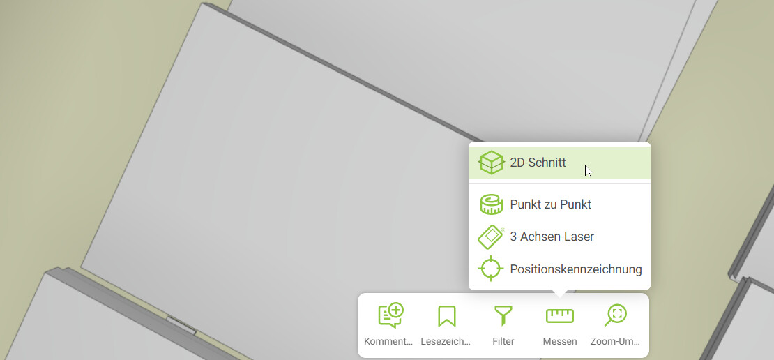
I would want to check orthogonal/free distances. Some tools don’t make it easy for the user. We are very fond of how BIMcollab Zoom is doing it. Especially the user-friendliness of orthogonal dimensioning seems to be a pain in many other platforms … for example, Dalux/Autodesks ACC are not that much but doing the job. The interesting aspect of BIMcollab is the changing indicator style of the cursor
B. Coordinates and Anntotations
Coordinates of points might be interesting too, especially when dealing with infrastructure or irregular buildings with multiple height jumps of the floor slabs. This is also missing in BIMcollab. Solibri allows for it with a Markup
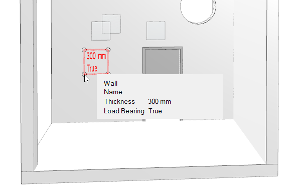
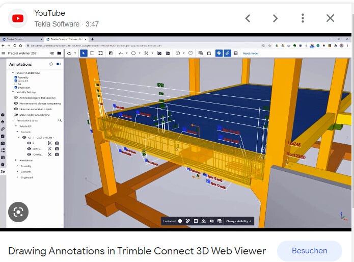
This is basically for figuring out geometry as the dimensions are not shown like with drawings. Dimension lines are super important for having the impression of how big this stuff you are seeing actually is. Additionally, it can be used like for redlining … please change this dimension shown to value x. People in our office complain that the dimensions in the IFC Viewers (in the majority of them) vanish, which means they cannot prepare views and have to redo the stuff regularly. Compared to authoring tools it is super inconvenient for them to handle dimensioning in viewers, which is the reason why they prefer doing it in PDF, Autocad etc.. One of the benefits of Trimble Connect is that dimension lines can be transferred from Tekla. It helped our guys massively in a model-based review process of the execution drawings of a steel contractor.
I would see it as something which is attached to a view and something which can be stored. The current views are transferred by the connector of the authoring tool but don’t show the filtering and visibility settings of the authoring tool … it is nice but not the full package. It would be super cool if people would be able to additionally create their favorite views by themselves. Maybe coupled with view filters (coloring), manual coloring, and proper tree-wise hiding/unhiding (we talked about the flexible tree selector in our call). This means the guys handling the viewer are able to prepare something they are allowed to keep. By creating a comment in this prepared view, the dimensions are shown too in the comment. Would probably help to increase the adoption of it. A lot of our guys very much dislike the “we are not allowed to keep it” part of the existing 3d viewers.
I hope this helps. If you need further feedback, please let me know and we can go for a talk.
Best,
Alex
some additions of how it looks like in:
Dalux:
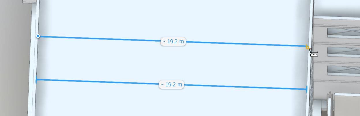
Yellow rectangular indicator icon to show that the dimension is orthogonal. Yellow is not that great of a color as an indicator.
Dalux also uses the 2D section function … a modification of their 3D section but with black section cut lines for the section plane. Gives one more the vibe of a drawing people tend to love.
Autodesk ACC:
The orange rectangular indicator icon is a bit clearer. The rounding symbol (~) can give one the impression of not having an accurate dimension. I’m not sure if a caught the proper line/edge is the fear one might get by dimensioning.
Agree with @AlexHofbeck s examples!
About the Dalux-like 2D drawings in the 3D model that’s a really appreciated feature… ![]() We’re working on being more data and 3D driven, though sometimes we need to take a hybrid approach and use eg 2D views in eg Revit to be able to work with eg measurements, text and annotations in a feasible way… If we could commit and measure 2D drawings (eg dwg or similar) or even better bring/convert 2D elements like text, annotations and similar to 3D views/visible objects somehow (like in @AlexHofbeck s Tekla/Trimble connect example) it would be really valuable and increase adoption.
We’re working on being more data and 3D driven, though sometimes we need to take a hybrid approach and use eg 2D views in eg Revit to be able to work with eg measurements, text and annotations in a feasible way… If we could commit and measure 2D drawings (eg dwg or similar) or even better bring/convert 2D elements like text, annotations and similar to 3D views/visible objects somehow (like in @AlexHofbeck s Tekla/Trimble connect example) it would be really valuable and increase adoption.
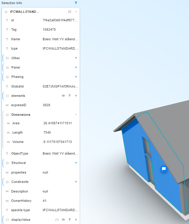
We mostly take simple measures by clicking in the model, a good snapping function and cursor makes a big difference. Mostly distance between two points, chain distances and area measurements. Also getting fast values like areas or perimeter by selecting an object eg a room is useful, similar to the current feature:
(Side question, I know how to isolate an object and view only that in the viewer, but how can I instead hide that object and show the rest of the objects? Eg hiding the roof?)
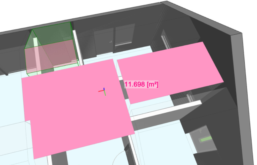
Agree with @AlexHofbeck s examples, and adding summing (eg areas) of clicked objects :
Would be great to attach a measurement to a comment or similar as a way to save it. It would also be useful to be able to tag measurements/comments to find them easier (ie we have some defined measurements that we work with on every project and it would be great to be able to search for eg measurement with tag “distanceToFireplace” on stream “nameOfStream”).
Hope helps, excitied to follow this!
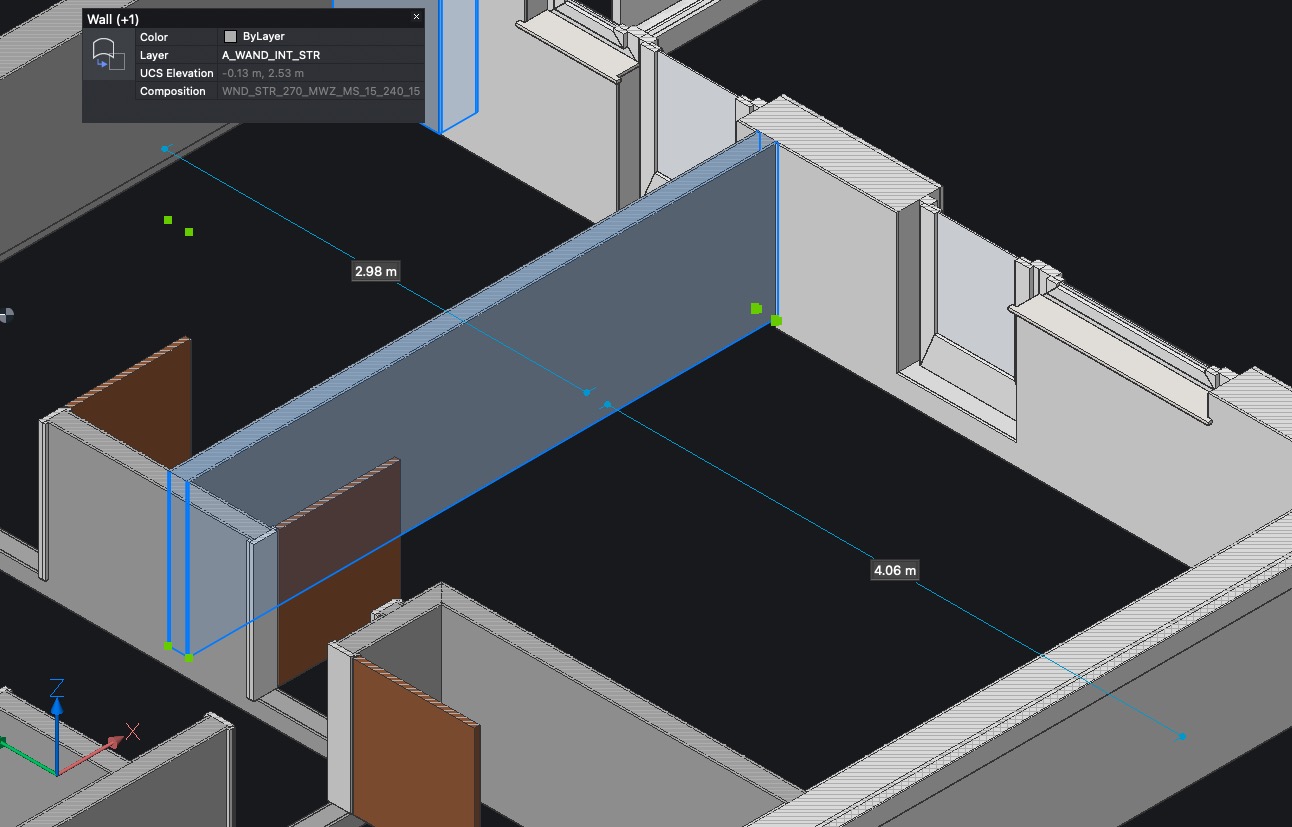
I like the Bricscad way.
Just select a Solid and you will get 2 measurements in both directions
to its neighbored Solids. It is called DYNDIM (dynamic dymensions).
You can control their location by which Face and where exactly you click
to get the desired next elements.
(And you can edit one of the values to change the Solids position or move it)
@zoomer: I like this
It is similar in Revit … that would be really cool ![]() .
.
Dalux has a 3-way laser distance measurement, which goes in a similar direction. Select a point and it makes rays in x, y, z axis to show distances to the next surface it hits.
The struggle with the above is like always the rotated coordinate system (north angle ![]() ) so dimension lines are not rotated
) so dimension lines are not rotated ![]() … but you get the gist
… but you get the gist
Hey all in this thread, @alex is making some progress on the measurement tool we’d like to share with y’all. Remember, POC warning applies.
We’ve looked at several paradigms of measuring things around, matched those with our constraints (e.g., we need to operate on meshes, there’s no edges info, etc.)
What we’re attempting to do in the MVP is:
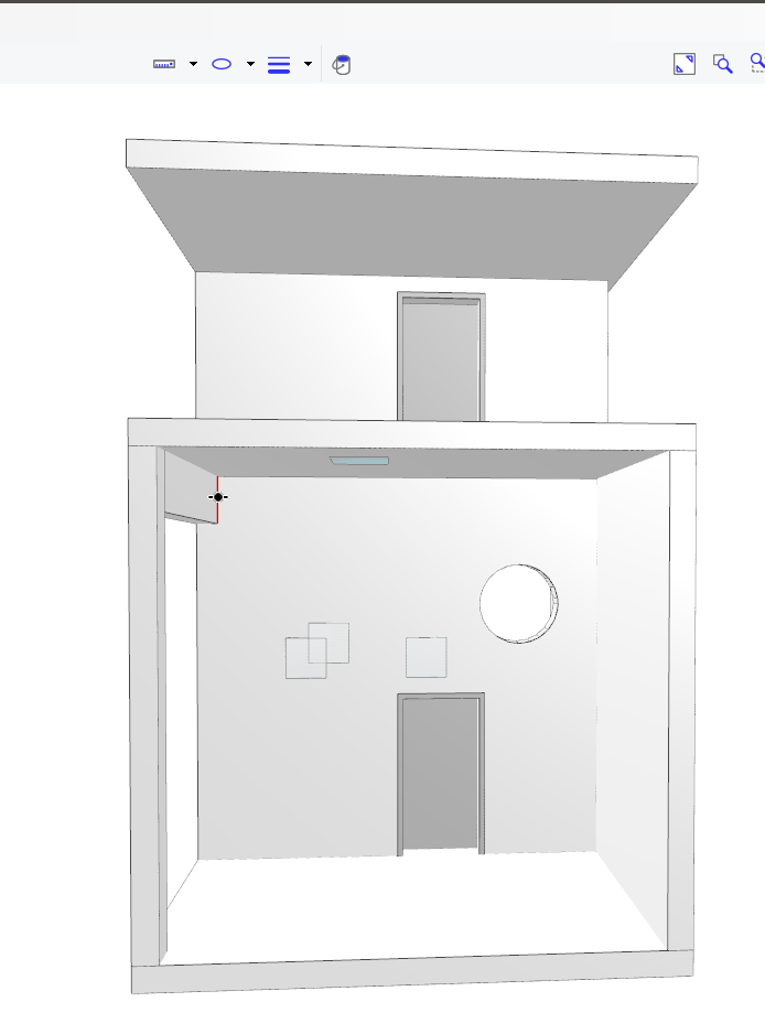
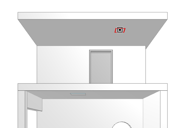
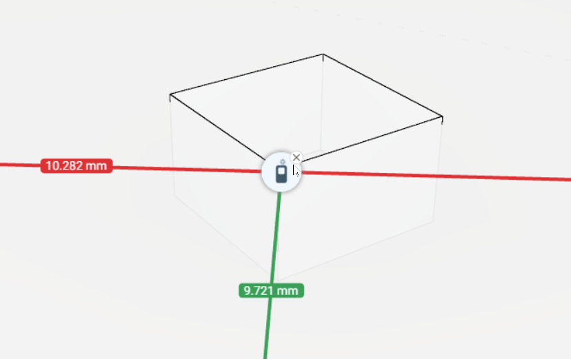
Here’s a video of the constrained perpendicular mode:
Heavily inspired from Navis - thanks to @jonathon for the patience to walk us through it - the UX flow is:
Note, in the unconstrained mode, you won’t be restricted to the object’s face normal.
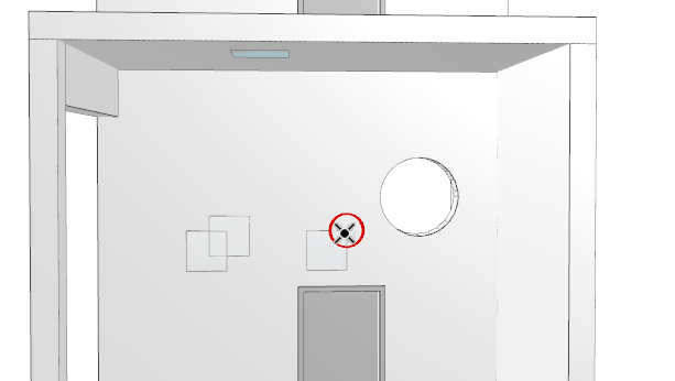
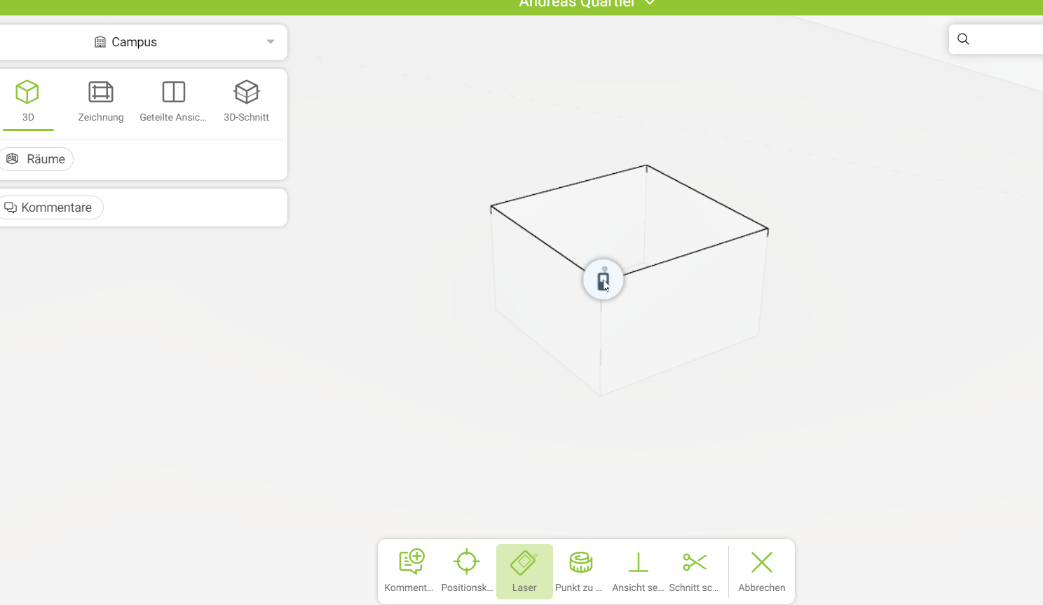
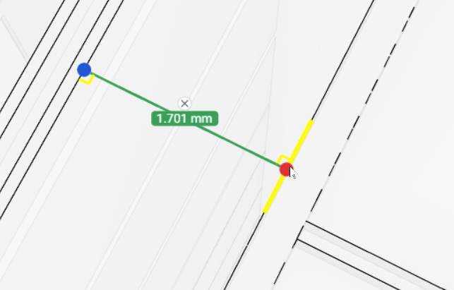
The auto lazer mode works like this:
And it’s basically a “double click” (or shift click) on a face to get a measurement based on the first instersection across that normal that we find. I find it super cool because for really simple on the fly dimensioning it’s saving quite a lot of time and clicks!
PS: Happy Friday y’all ![]()
This is absolutely great !
Reminds me of one of the best new Bricscad Features.
Little different,
(in Bricscad you just select a Solid/BIM Object, depending on where/which Face
you clicked, you will get 2 dynamic dimensions to the next neighbored Objects
Faces …)
But I like the implementation showed too !
Very logical UI/UX.
It is so inspiring what Speckly Team and even externals did lately.
![]()
Hello!
Amazing job.
It looks promising!
Both functions looks really well suitable for quick checks and communications.
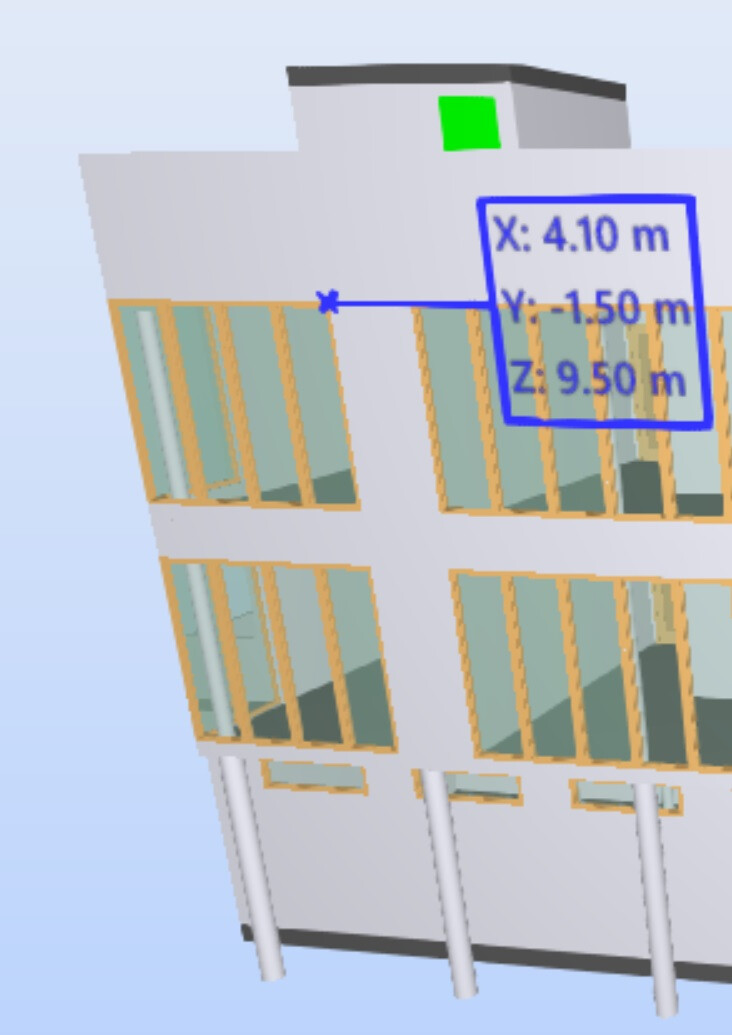
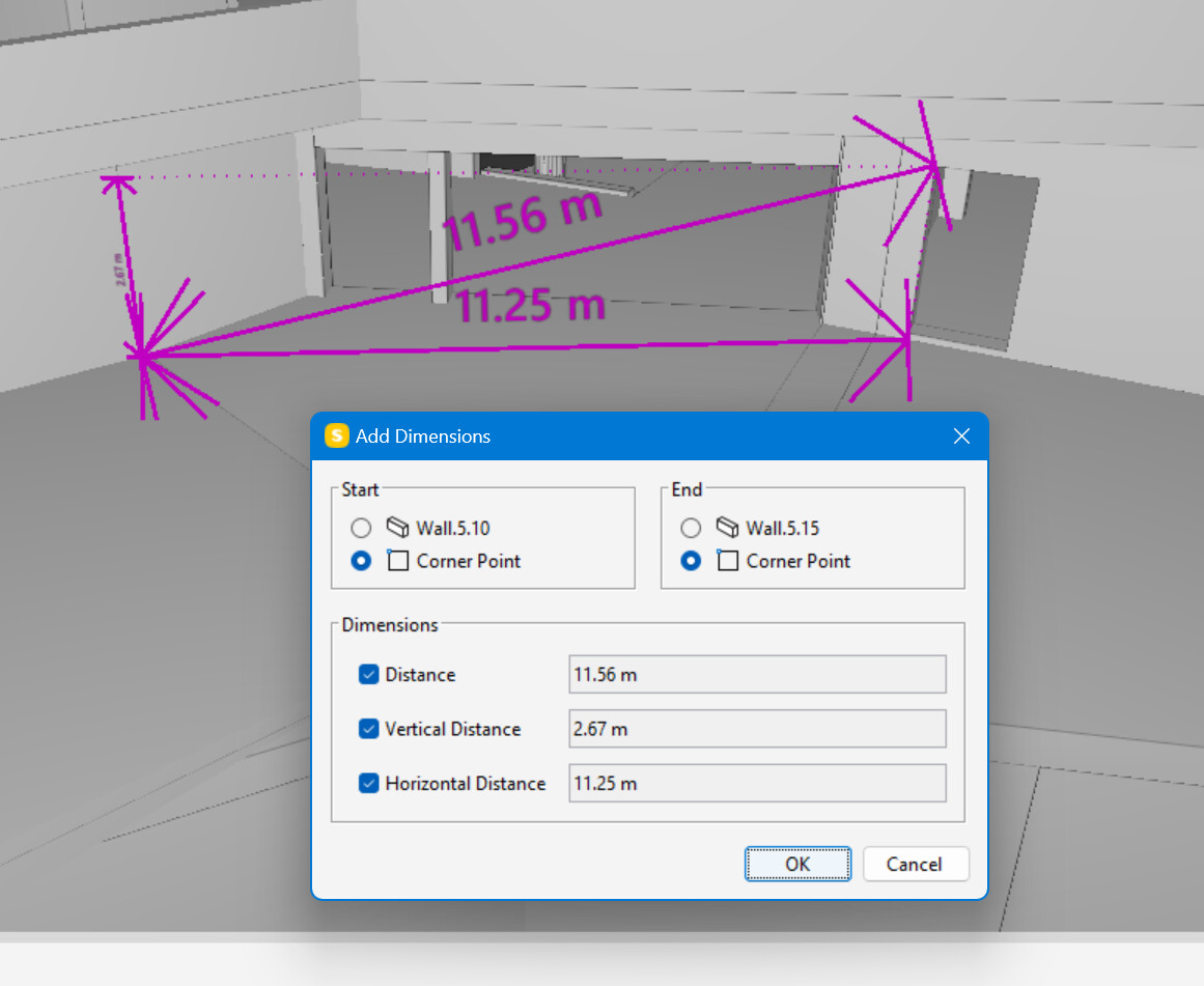
Would be nice if the unconstrained 2 points measurement would give the linear point to point distance but also the vertical dimension and horizontal dimension. Maybe as an option?
A bit like what Solibri does :
Definitely looking forward to those features!
Thanks
Hi Dimitrie, any update about the measurement tool?
Thanks
@mirko.maccarronello , This is live at app.speckle.systems:
Hey @mirko.maccarronello ,
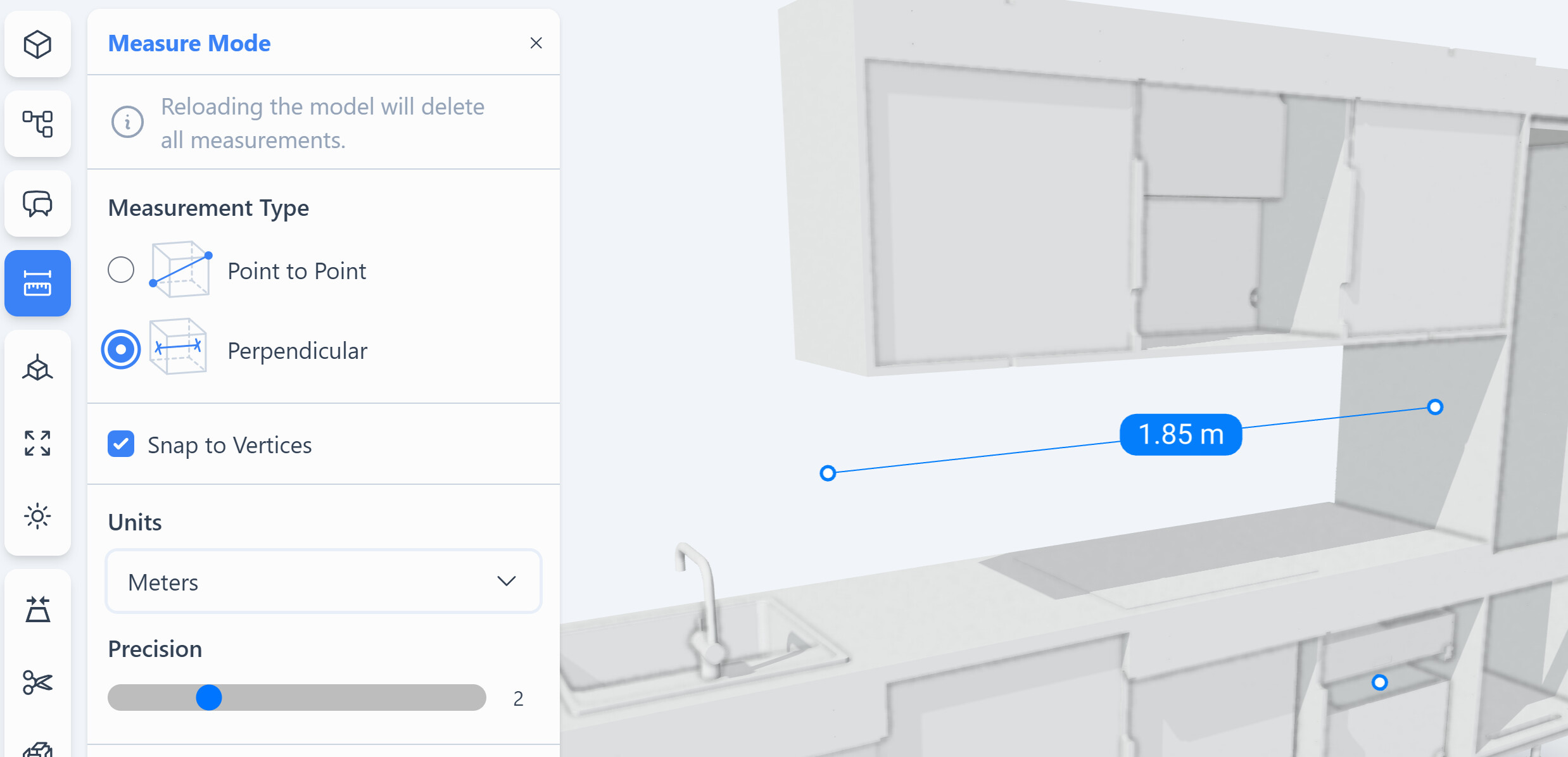
We are pleased to announce that the measurement tool is now live and available on our new front-end. To access it, simply visit app.speckle.systems. It is worth noting that this new front-end utilizes the same database as speckle.xyz. We encourage you to try it out and share any feedback you may have with us.
Very nice. sorry I lost your communication on it. So app.speckle.systems will replace speckle.xyz or what? now I have two different account with the same email for each platform, I have to remove one?

Hey there @mirko.maccarronello!
No worries, you don’t have to remove anything. Right now, the stable front-end is speckle.xyz, but app.speckle.systems will replace it in the future (eventually). I shared app.speckle.systems with you because you were looking for the measurements tool, which is currently only available there. The good news is that both speckle.xyz and app.speckle.systems use the same database, so anything you sent to speckle.xyz is also available on app.speckle.systems.
OK thanks, so for the moment I keep 2 different accounts?
You can remove app.speckle.systems account. You will still be able to use app.speckle.systems.
Or the other way around - if you aren’t using the embedded viewer, FE2 is feature-complete with respect to FE1.
We are still actively developing FE2 - expect to see many improvements in 2024, all your feedback is welcomed.