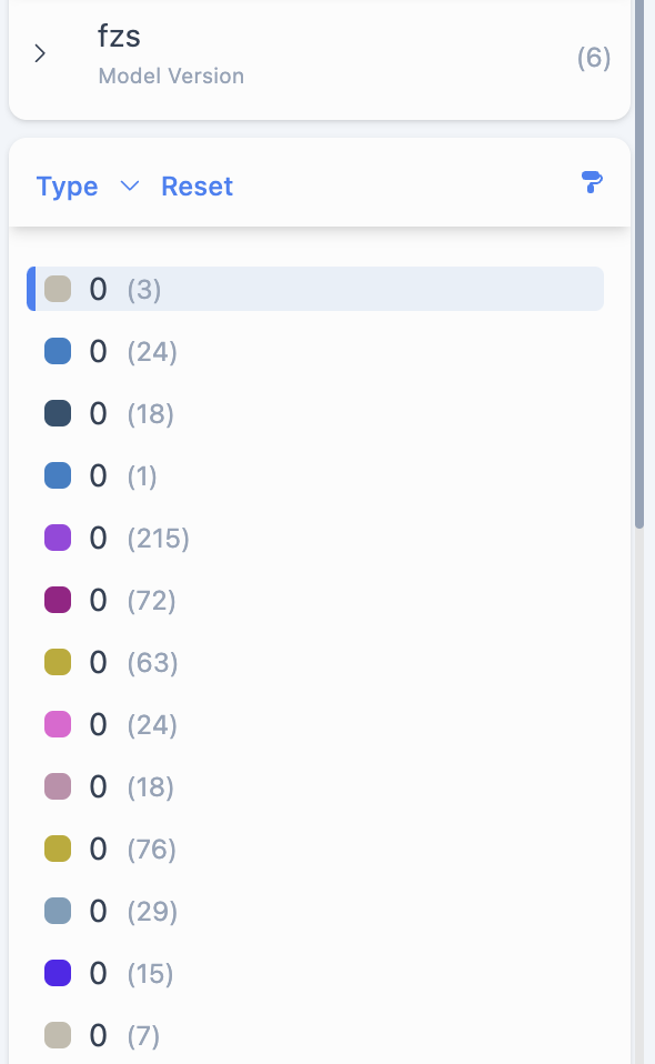
Legend for Decimal numbers and Shuffle mode for coloring
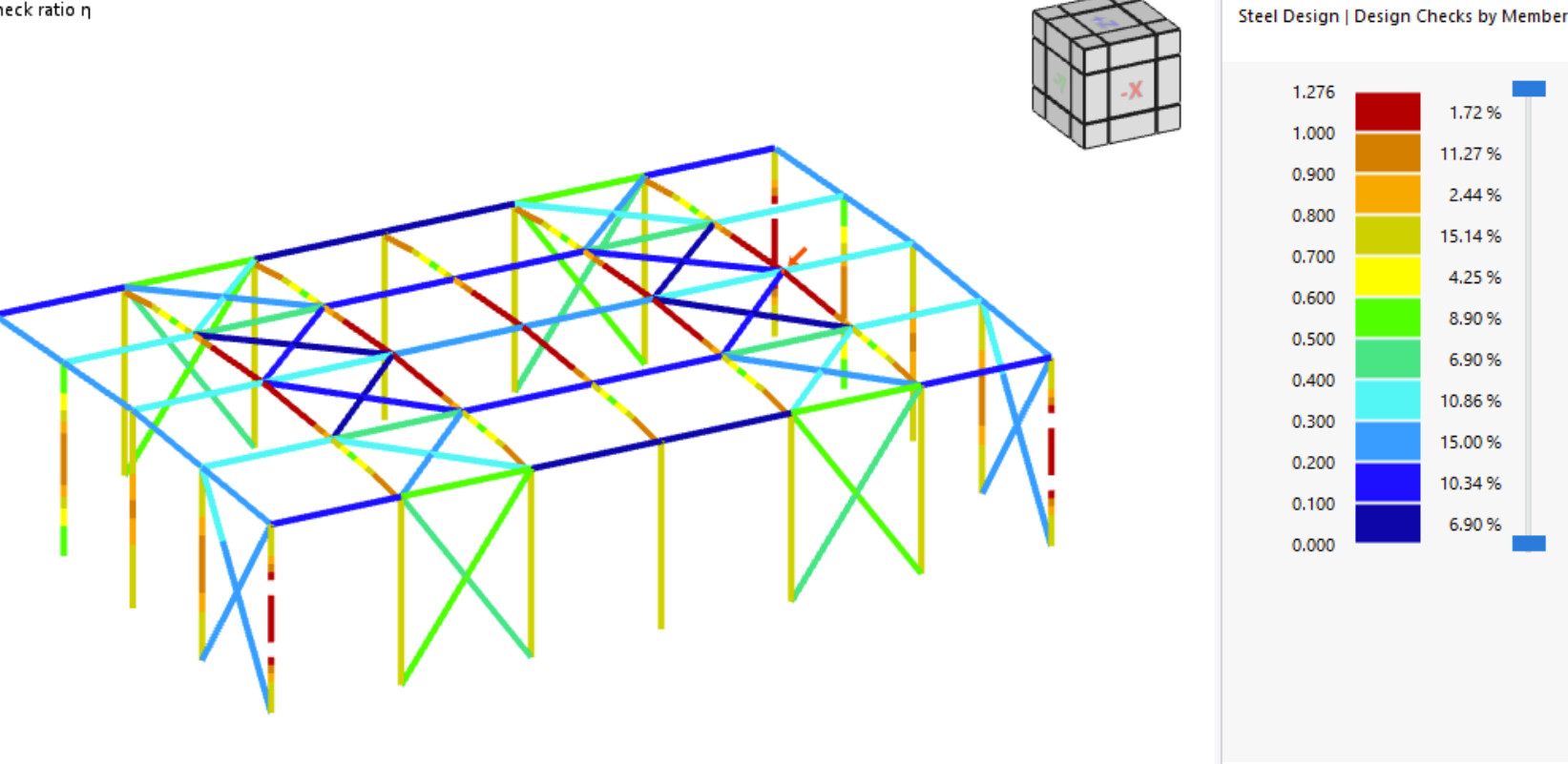
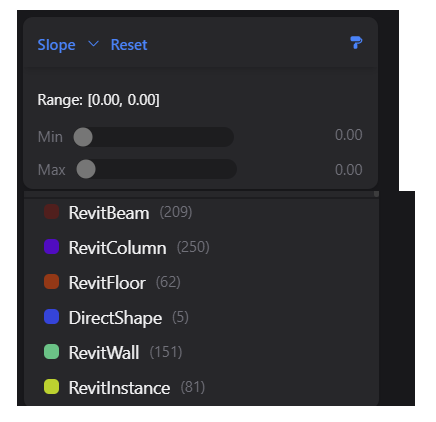
the filter range is already pretty good, but as the colours are also indicators to see the distribution it would be good to also show the distribution legend like for the text parameters. A legend would also help with Finite Element results.
Additionally, it would be great to have an optional shuffle mode for the colouring so that the colour distribution is not linear but random. This helps for example if you want to check height jumps in a slab (colours of neighbour elements have more variance and you see differences faster if the elements don’t have the same z-height).
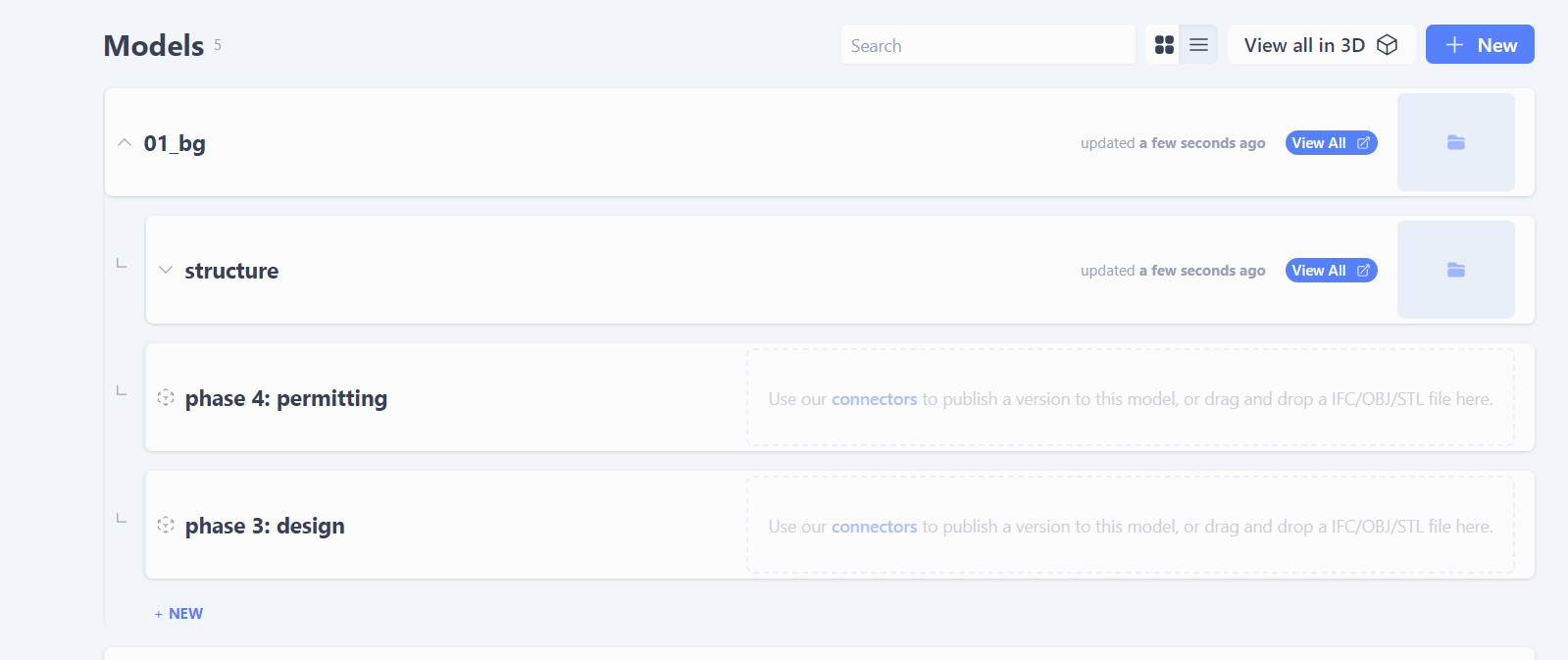
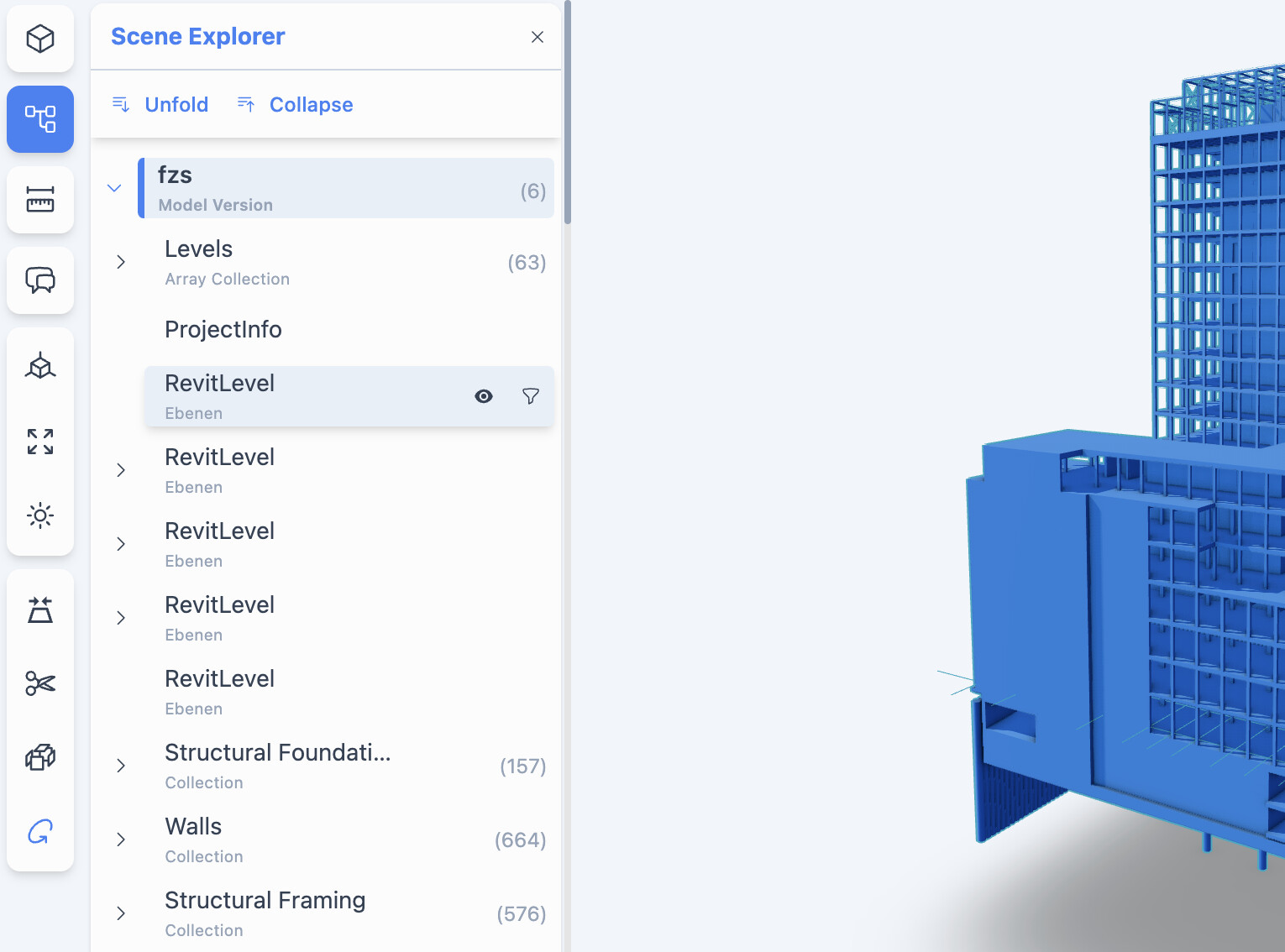
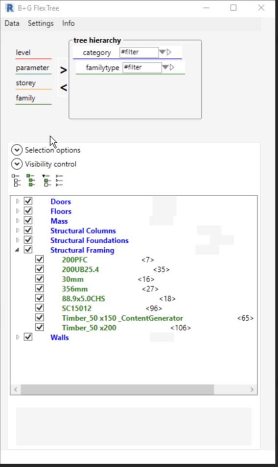
Confusing tree
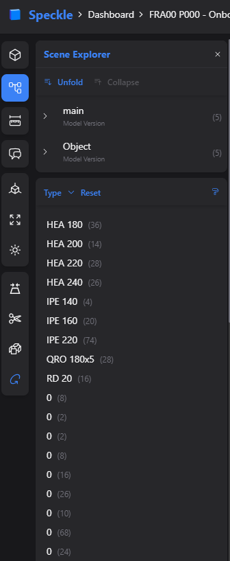
This model came from Revit. We have different level options some levels as a tree others without sub-hierarchy and then all the other categories below. This will be super confusing and not helpful for the users. As mentioned in the past a tree like in the IFC would be super helpful, otherwise people will have a hard time navigating.
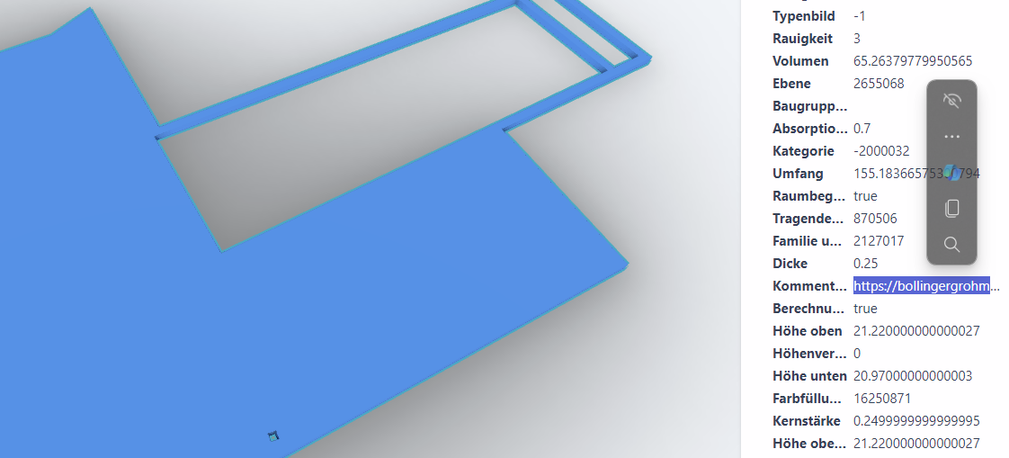
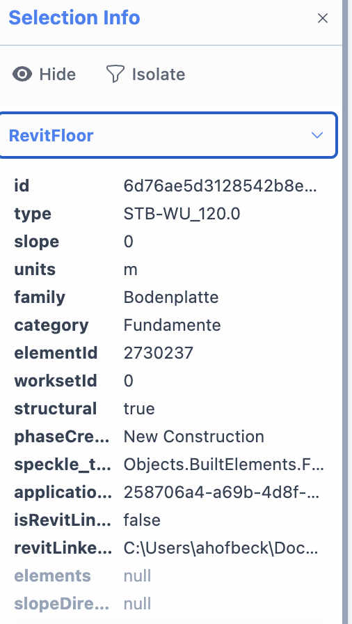
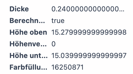
Rounded decimals
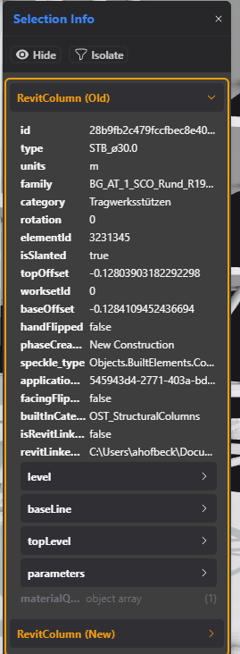
when you are showing that many decimals people will make direct assumptions (judgement in the worst case) about the inaccuracy of data which is sent to Speckle. An example is the top of the slab (Höhe oben). Rounded and three digits after the zero would be good then people don’t question the data … at least for the UI. .
### Addition ###: Shared Parameters can only be searched for the filtering with the ID of the parameter, not with their name. In the old frontend it was possible to search for the real name
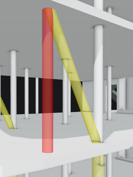
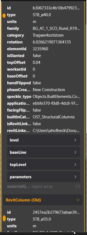
### Addition ###: Show volumes/area in the change comparison to understand, why this is a change … in this case the red column was deleted and the yellow one receives more m^3
In CAD I set 6-8 decimals - so that it jumps into my eye that something went wrong …
Better an option to deactivate trailing zeros … makes it even more flashy
If you are sure it not inaccuracy in CAD and only a translation issues in upstream to
Speckle, I do agree though and second an option to set number of decimals shown.
Second, my OK for preventing clients’s judgment.
My third reason is that 12+… or so redundant zeros do not really help legibility.
For CAD this is totally fine to have this precission (alligned to the other parties helps too ). In this case above, it is upstream to Speckle. As one is not able to differentiate between bad outside quality, I would round everything … because if it is already bad outside of Speckle, why should Speckle judge .
With that I agree:
At least from our point of view mostly non-CAD-users (project managers, project engineers) are accessing the viewer. If they see examples like the above, there is one or both of the scenarios below …
a) what are my people doing … this looks bad
b) Speckle is super inaccurate … please don’t use it anymore …
Scenario b) I want to prevent. It is as much a precision issue as with everything computer-based .
Just that 15,2799999999999998 triggered me.
As I so often got similar client’s geometry in the past. When I did the 3D
and snapped to their geoimetry I had to fight with boolean failings later.
And some users intentionally set tolerance to minimum decimals, to not
get bothered by own accuracy.
From this point of view I would like to make 18 decimals mandatory for
everyone in CAD environment. Maybe even mandatory use of snaps …
Decimal accuracy, if constrained at all, should be done so in relation to the tolerances. There are ANSI or ISO(DIN) standards for all of this. Having tackled these issues a million times over my career I’d prefer to apply a standard than either round arbitrarily or allow for custom truncation.
That said the tools we use vary enormously in the ability to work to standards. Coming from a longtime love affair with microstation has spoiled me with how accurate software can be so the Revit snap to orthogonal „feature“ is the most extremely bad version of this that I recall. While the ISO standard recommends 8 decimal point values for degree angles, try being any more accurate than 2 in Revit.
Accuracy greater than required tolerance can be problematic even before we cover unit conversions or binary to decimal conversion.
These are just my thought, the team will take your suggestions into consideration.
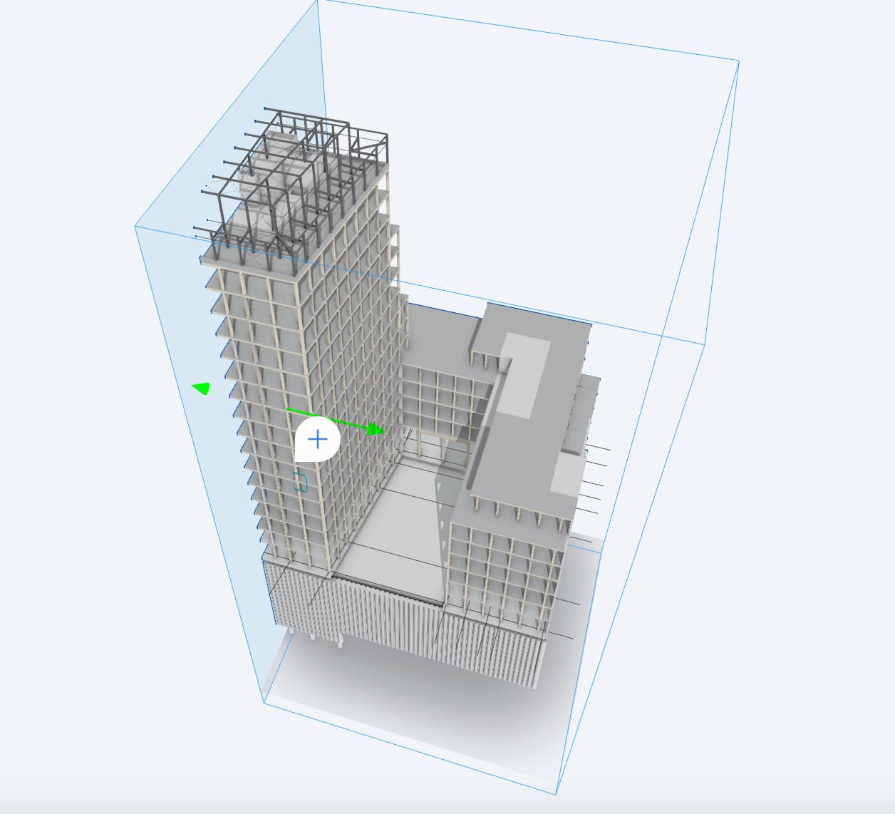
additionally to the above and referring to the 1) types … it seems that parts of the elements have values others do not. I’m not sure if it is related but @samberger has a similar topic. The model was uploaded yesterday with the latest connector version.
As there is quite a lot of points and now follow-ups for different items on the list we might get unstuck quickly. But lest give it a shot.
What you are describing is a classic histogram; would that be a helpful solution?
What options were selected as the criteria for sending that version from Revit? Selection, Category? And what version Revit Connector are you sending with?
Me too
Noted!
Noted!
Indeed, there is perhaps both:
more logical comparison points to be made on the diffing (though are you reporting that the diffing was incorrectly identifying?)
an indication of the points of difference (geometry, data, metadata)
Unclear if it is connected to @samberger 's issue - and I’m struggling to replicate your observed behaviour, which, given that it is a screenshot, is undeniable.
Could you share privately the model?
Part of me is suspecting localization but I hope not.
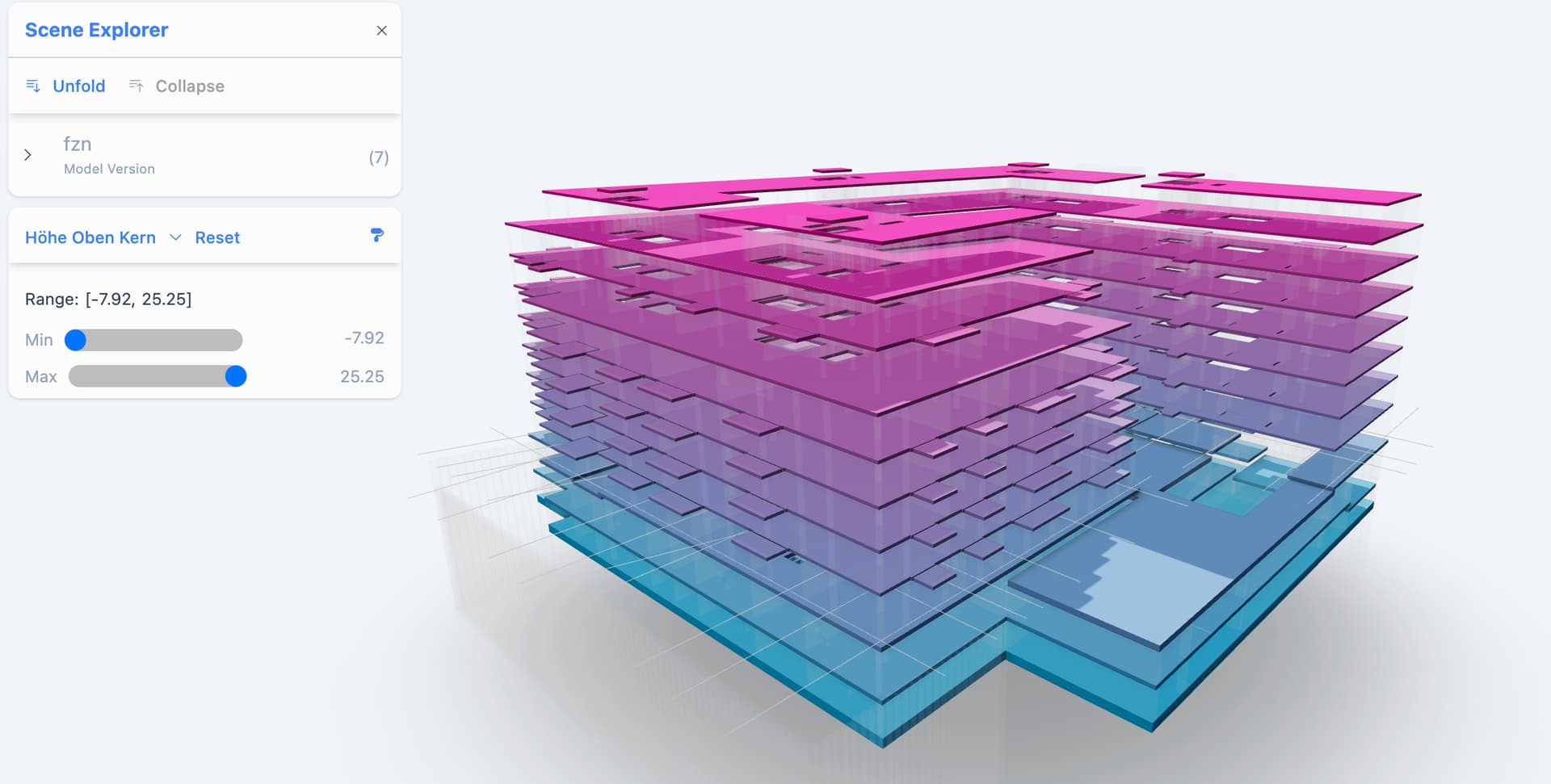
you have a min value, you have a max value … and maybe a slider for the steps between max and min.
your latest official Connectors 2.17.0, Selection with category to only send categories: Walls, Floors, Structural Columns, Stairs, Foundations, Structural Framing.
and here:
The diffing was fine … I wanted to say that volumes/quantities might be a good additional indicator for someone to check. This is not provided in the panel … might also make it too crowded. Maybe I also see it too much out of my perspective.
It would be cool to have an indicator to show where the data differentiates maybe like a yellow dot … or something more visible. Maybe only show what parameters/properties are different.
In the case of a more structured approach like the above, there might be the wish of the users to have a sorting by name (addtionally to date). Otherwise, it can be really confusing, especially with lots of models and submodels.
As hyperlinks can be really useful to link documents, say you have a refurbishment project, and you reference the old scanned drawings to a model element. We figured out the following points for you as feedback
It would be great to have a hyperlink function for parameter values … say the parameter value is in URL formatting it makes a clickable hyperlink in the properties menu
B: Hyperlinks as part of comments
By copying hyperlinks into the comments it shows it as black text but people don’t conclude that it is clickable. It would be great to highlight the hyperlink either by underlining it or by creating a border around it.
I was looking for a similar post made about URLs in comments in the legacy app. We certainly have a ticket for this, and the value is certainly appreciated.
I recalled security discussions of clickable URLs, but as I say, I can’t now find it.
Do you have any thoughts? Perhaps the collaborator role or above is a trusted source. URLs in data properties is tricker to validate the provenance of.
If I‘m not fantasizing the hyperlinks were a bit more visual in the comments of the legacy app … we were able to reference a product catalog for impact noise reduction onto a staircase and it looked clear that one could click on it. At least it was in my mind like this.
Regarding parameters and in general:
Maybe with an allow list under the admin settings … You define the URL which is allowed or blocked. By default everything is reduced/blocked
I will create tickets for both supporting hyperlinks in the selection info panel and in comments. We can consider any security problems when we pick them up.
 .
.