Speckle Community
Viewer Measurements
Features & Ideas
viewer
jonathon
(Jonathon)
18 December 2023 13:52
14
@mirko.maccarronello
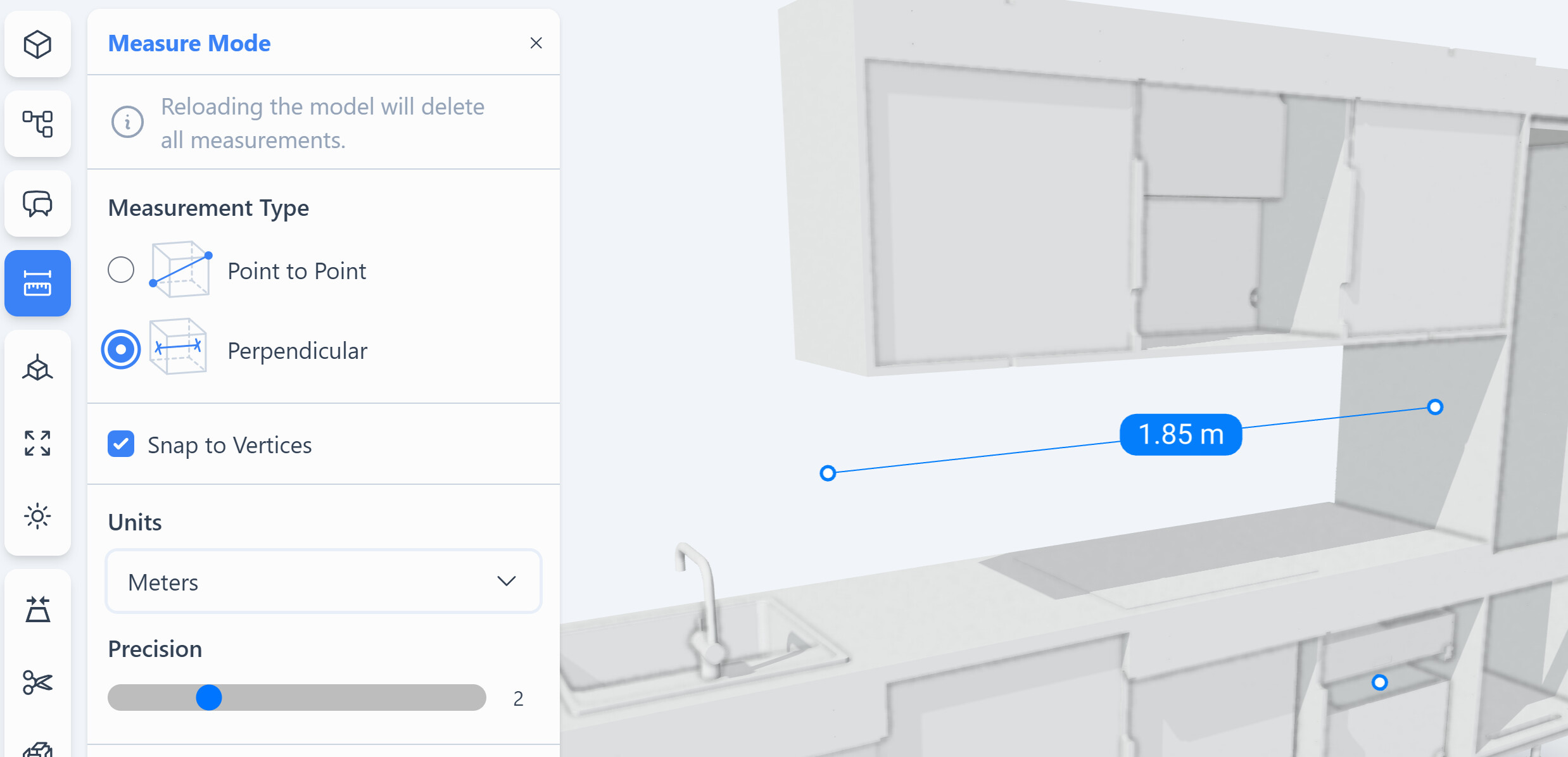
, This is live at
app.speckle.systems
:
image
2476×1196 207 KB
3 Likes
show post in topic