I have been trying to get to the bottom of why my Meshes are borked. I have a simple example and would appreciate some simple guidance. As background, I have been translating my knowledge of Mesh definition from BabyloJS and can appreciate that it would be different for Speckle.
Mesh Scenario 1 (One mesh per triangle):
// Triangle 1
vertices = new List<double> { 0, 0, 0, 1, 0, 0, 0, 1, 0, };
faces = new List<int> { 0, 1, 2,};

Objects.Geometry.Mesh baseMesh = new Objects.Geometry.Mesh( vertices, faces );
baseMeshes.Add( baseMesh );

// Triangle 2
vertices = new List<double> {  0, 0, 0, 0, 0, 1, 1, 1, 0 } ;
faces = new List<int> { 0, 1, 2,  } ;

Objects.Geometry.Mesh baseMesh = new Objects.Geometry.Mesh( vertices, faces );
baseMesh[ "renderMaterial" ] = TranslateMaterial( geom );
baseMeshes.Add( baseMesh );
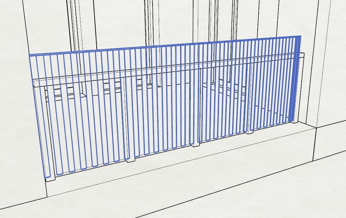
Success  but is it a problem for the viewer handling large
 displayValue arrays?
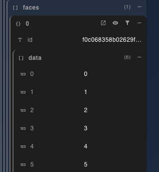
Mesh Scenario 2 (Single mesh two triangles):
// Triangle 1
vertices = new List<double> { 0, 0, 0, 1, 0, 0, 0, 1, 0, };
faces = new List<int> { 0, 1, 2,};

// Append Triangle 2 vertices
vertices = new List<double> {  0, 0, 0, 0, 0, 1, 1, 1, 0 } ;
faces = new List<int> { 3, 4, 5,  } ;

Objects.Geometry.Mesh baseMesh = new Objects.Geometry.Mesh( vertices, faces );
baseMeshes.Add( baseMesh );
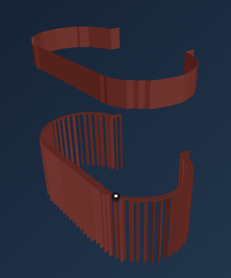
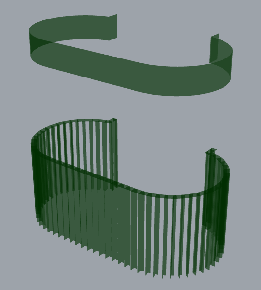
Fail