I’ve been diving into Speckle, and so far it’s awesome. I managed to send and receive different types of data to my streams using applications and their connectors. I also managed to receive and send those objects using a Python script. Right now I’m trying to combine different objects in Python (experimenting with detached properties, and stuff like that) from different streams into a new stream.
Basically, this worked. The thing is, one of the objects is a 2D GIS map, which I grabbed from an api and put into one of my streams. The other object is a 3D object (basically a house), which I put into another stream. I retrieved both objects in my Python script, combined the two into one Base object, and committed this to a new stream.
In this new stream, I can indeed see the two combined objects in the data view. The 3D viewer, however, renders the GIS data, but very far away. This GIS data is basically a street plan of an area of a square kilometer, and contains coordinates. It is my guess that my 3D object is also present, but very small compared to the GIS data, and probably placed at completely different coordinates.
My question is: can I (programmatically) alter my 3D object so that its x and y coordinates fall within the plane of the GIS data? I’ve seen a tutorial in which this is done using Rhino, QGIS and Grasshopper, I was just wondering if I could do this with Python.
I really hope this is a somewhat coherent story. Maybe I’m approaching this the wrong way, but I’m still in the process of getting a basic grasp of Speckle.
Thanks in advance!
edit: I’ve seen that the GIS data contains a ‘crs’ field, which is apparantly a Speckle object. I’ve tried transferring this field into the 3D object, but it gave no result.
Hey Kevin. You are throwing yourself straight into the deep end.
What you describe should be possible. From what I am reading, you have 2 separate questions, albeit you have answered one yourself. So I’ll answer that first with a question.
What are you trying to combine streams for as a high-level macro task? It is possible, as you’ve seen, but it might not always be necessary. Downstream applications can separately subscribe/receive multiple streams. This can often be a good way of segregating work.
The second point is more straightforwardly likely to be simply a distance from the 0,0 origin issue. GIS data is quite often in “real-world” coordinate space, and the software is designed to cope with the large numbers that imply. 3D authoring packages (you don’t say how the house was generated) tend to have internal mechanisms to author as close to the model origin as possible to make the math easier.
Could you share the Stream with us (it can be a private message if you prefer)
The embedded CRS property is embedding in the GIS file what projection of mapping is used (different maps exist to translate the globe to a flat surface).
Depending on the sources you are using, there are two ways to tackle this.
In Revit Connector (I’m making an assumption here) you can send to Speckle using a different origin that has been set to translate the model to real-world coordinates. This would bring that model => to the GIS.
In the GIS connectors, you can do the inverse and set an artificial projection that translates a nominated coordinate to be the origin and send the GIS CAD => the model.
Doing all that in python IS possible, but the geometric definitions are manifold in a Speckle object. You would have to apply the same transformation to the BoundingBoxes, all the base geometry and then Mesh Geometry of every object. Much easier to author consistently and pick which coordinate space the models will live in
For context: I’m a student software developer, and I’m interested in working with geodata and app development. I am, by no means, an expert in the GIS or 3D modeling field. Hence my question; how much can be done using the SDK?
As for the workflow, the GIS data is provided for free by my government, and can be edited by open source software (I’ve installed QGIS), so that’s fairly easy. However, the 3D part is trickier for me. The sample model I used indeed originates from Revit, but I have no access to that application. Many applications are way too expensive, and/or offer no free trials. For uploading to my Stream, I used a combination of Blender and Rhino, of which the latter will soon expire.
I guess what I’m aiming for is combining GIS data of my neighbourhood, adding some models on top of it, and sending the combined output to Unity. One of the layers in the GIS data is land register data, so basically points where a house address is registered. I thought it would maybe possible to put some 100 3D objects centered on those points, as a first test, using Python and loops.
I’m still in the exploring phase, so I’m also just trying to see what Speckle is capable of.
Thanks for your advice, I’ll go and fiddle with it some more.
I’m reusing this thread for a follow-up question if that’s okay!
So after the helpful tips of Jonathon, I’ve indeed focused on working with coordinates in the applications. I’ve followed a few tutorials, and managed to add a georeference to my model (using the BlenderBIM plugin). This model was imported as an IFC4 file into Blender.
However, when I upload my model using the connector, it appears that no geodata has been included. Should this be possible from Blender? Or did I do something wrong? I’ve been struggling with this for a few days now.
I also managed to get a student license for Revit, and I tried sending the model from there, but this gives the same result.
Hey @kevinpease, nice to see you persevering, and I commiserate you don’t see the results you want.
Where do you want all these combined models to end up? Both in terms of what software and which location.
I’m not familiar with the metadata handling in Blender Connector, but do you want to send Blender geometry to QGIS?
If you want to end up in Blender and then the viewer, I think your easiest first step is to export from QGIS with the artificial CRS, which will map that to a known point near zero.
If you are determined to end up in real-world space with your 3D data, the Revit route should have worked for you. The trick is specifying a point in the Revit model as a known coordinate and setting that as the Project Basepoint with the real-world coordinates. On export from Revit, under Advanced Settings, you select export to Project Basepoint.
All this is tricky. When I have some moments in the New Year, I will look at some of this GIS interop and get it into our tutorials.
Thank you for your quick answer! I want the data to end up in Speckle, and eventually in a Unity app.
I followed your tip, by setting the GIS data to zero, and this way, it combined neatly with my 3d model. So now I want to move the model to its real-world coordinates. As a demo, I was aiming to combine everything in one commit, so that I have a basic representation.
On export from Revit, under Advanced Settings, you select export to Project Basepoint.
I haven’t tried this yet, will fiddle with it some more. Today is my last day before the holidays, so I’ll dive into it deeper next year.
Again, thank you so much for help, happy holidays!
I’ve tried several ways to georeference a model (of any kind, really) and upload it to Speckle. Unfortunately I haven’t succeeded yet. I’m not sure what I was doing wrong, but I decided to let it rest for a bit. I did find some new tutorials, so I’ll try it again soon.
In the mean time, I used 3D data from a WFS api, which already came georeferenced. I was able to combine this with 2D GIS data, resulting in a map of an area with some buildings drawn on top of it. All of this is done in a standalone script, by directly interacting with the QGIS api, and using several functions of the QGIS Speckle connector. Pretty neat!
But yes, I’d love to get my hands on a proper georeferenced BIM model (e.g. a real house) so I can place it on my combined 2D/3D map as well.
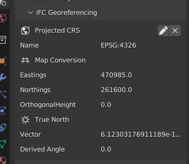
So I gave it another try. I opened my Revit model, and followed this awesome tutorial by Dion Moult to add coordinates to my project base point. As a check, I exported this to a IFC4 file (still following the tutorial) and opened it with Blender+BlenderBIM plugin. It seemed I finally had my georeferenced file, but uploading it to Speckle directly from Blender put the model back at coordinates 0,0. It was my guess that the Blender Connector doesn’t transfer coordinate information, which would be understandable, given that this is handled by the BlenderBIM plugin.
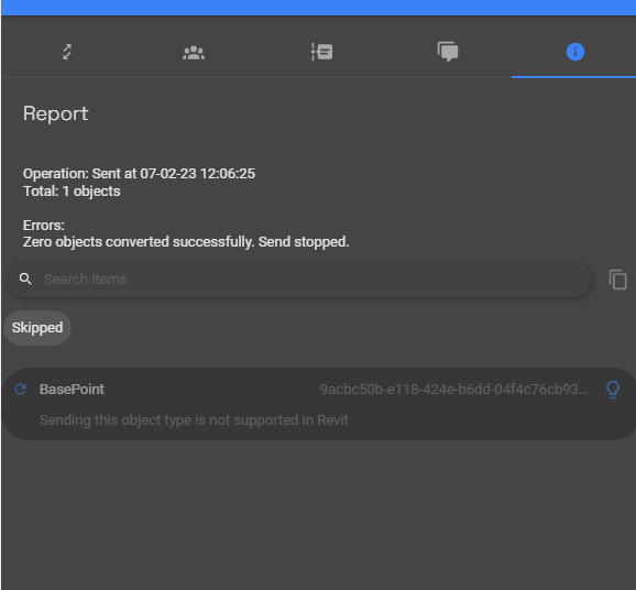
I then tried uploading directly from Revit using the Speckle Connector, but it gave me this error:
So apparently the Speckle Connector doesn’t support modified base points? I’m using the 2023 version of Revit, and different Connector versions (including the newest). Uploading the original Revit file using the Revit Connector without the added coordinates is no problem.
As a final resort, I tried directly importing it through the ‘Import File’ function on the website, but it always results in an error. It doesn’t time out and the file itself is only 4.4MB. I also tried it with a IFC2x3 version, but it still fails. These are the IFC files that have been exported by my Revit installation.
Are there any more ways I could try, to get a georeferenced BIM model in Speckle? (Preferrably a workflow that can handle either Revit files or IFC)
The BasePoint not converting is unconnected with you changing its coordinates of it. In your screenshot, it seems you have selected just the Basepoint to send. You say unamended values of Basepoint allowed for its conversion. I don’t think this is correct.
SpeckleBlender has no concept of Coordinate Reference Systems, so that it will export relative to Blender 0,0,0
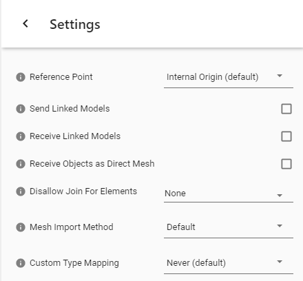
To Export from Revit, if you have set the Basepoint’s coordinates but not moved it from the origin, you’ll want to export relative to the BasePoint in Revit Connector. This will result in no horizontal translation when received in Blender 0,0,0. If you want the model located relative to the Mapping Grid, select Survey Point in the Revit Send options.
You have previously said you want all of these datasets to end up in Unity via Speckle. Therefore the setup of the Basepoint exercise within Revit will allow ingress back to Revit while retaining the geometry at 0,0 for Unity.
Revit: Specify real-world Basepoint coordinates for your EPSG project and export to Speckle relative to Base Point (the IFC4 Method into Blender if you wish)
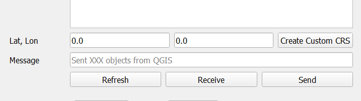
QGIS: Again, with the mapping data in QGIS with the CRS for the same EPSG, set the same coordinate as the custom CRS setting in the Speckle Connector you set in Revit.
Both your data streams will converge in Speckle at 0,0 and from there into Unity.
Any edits to the geometry you make in Blender or BlenderBIM other than changing the georeferencing will not change this setup.
There are further discussions around Grid North vs Geodetic North, but if your ambition is colocated data in Unity, I’m presuming this is not a concern.
Thank you for your endless patience. You’re right, I tried to send only the Base Point It works now.
As for the georeferencing part, I think I finally have a basic grasp what the difference is between a Base Point and a Survey Point, and what they’re for. I think I had false expectations as to how this all translates to Speckle:
Upon analyzing uploaded GIS data in Speckle, I noticed that the geometry of the elements have large numbers as coordinates, which translate to the real world coordinates. These numbers are in the same range as the coordinates of the same data in QGis.
It was my expectation that BIM models from Revit would also behave in this manner. I thought that georeferenced models (using either Base Point or Survey Point) would be translated to the coordinates (as specified in the Revit Base Point or Survey Point) when uploaded to Speckle. Of course, selecting the proper settings in the Speckle Connector. Instead, this happens.
What I’m trying to achieve is a 2D map with my GIS data, retaining original coordinates, and on top of that BIM models, in their correct locations, using these real world coordinates.
Would I need to move the model itself to those coordinates? If I know the coordinates, maybe I could write something myself for that. I managed to put the GIS data at the origin, but this way the geographic data is lost.
Thanks again for your help and patience. I’m still trying to figure out all of this stuff.
ps: I’ve put the Unity idea out of my head for now, as things are complicated enough as they are
I can’t believe it, you’re right! I hadn’t noticed it in the Revit interface. Also, your suggestion of using a survey point and selecting it in the Speckle Connector enabled me to achieve what I wanted.
I’ll try to highlight an answer to mark this thread as ‘solved’ but to be honest, this entire thread has been a learning path of its own. I’ll try doing cool things with Speckle and will probably ask more questions again in the future.
i’m an architect trying do do similar stuff but relatively new to coding. for help in that manner,
do you have a git-repo or other sources that you could point to?
@kevinpease can of course answer your question, but perhaps we can help too; Are you looking to geolocate Speckle data in code or move from one application to another?
I’m sorry for the late response. I have been researching this topic for several months now, so it’s kind of hard to point you to resources. There’s loads of them, and very context-dependent.
What are you trying to do exactly? It heavily depends on the file types and their associated applications what you can do with the data, and how you should handle it.
A good place to start is to dive into the Speckle Dev Docs, there are some tutorials in there which will teach you to write a simple script (either in Python or C#) that lets you upload and download Speckle data, create commits etc. Once you have that going, you can look into specifics.
I don’t have anything useful on Github right now, just some local test scripts. But yeah, try to formulate what it is you want to do, and maybe see if you can find a workflow that makes use of the existing Connectors. That’s the easiest way to go, if possible.