I am working at an engineering firm in the Netherlands.
We make technical designs of civil structures like bridge and tunnels.
In the design phase we are always struggling with interoperability of the design other design disciplines.
Like road and rail design. Most of the time that is because their design software isn’t Revit.
Importing and exporting files from an into Revit is a pain, and takes up a lot of time.
Especially when design iterations are happening al the time.
We are looking at Speckle to maybe streamline this process. And make it more manageable.
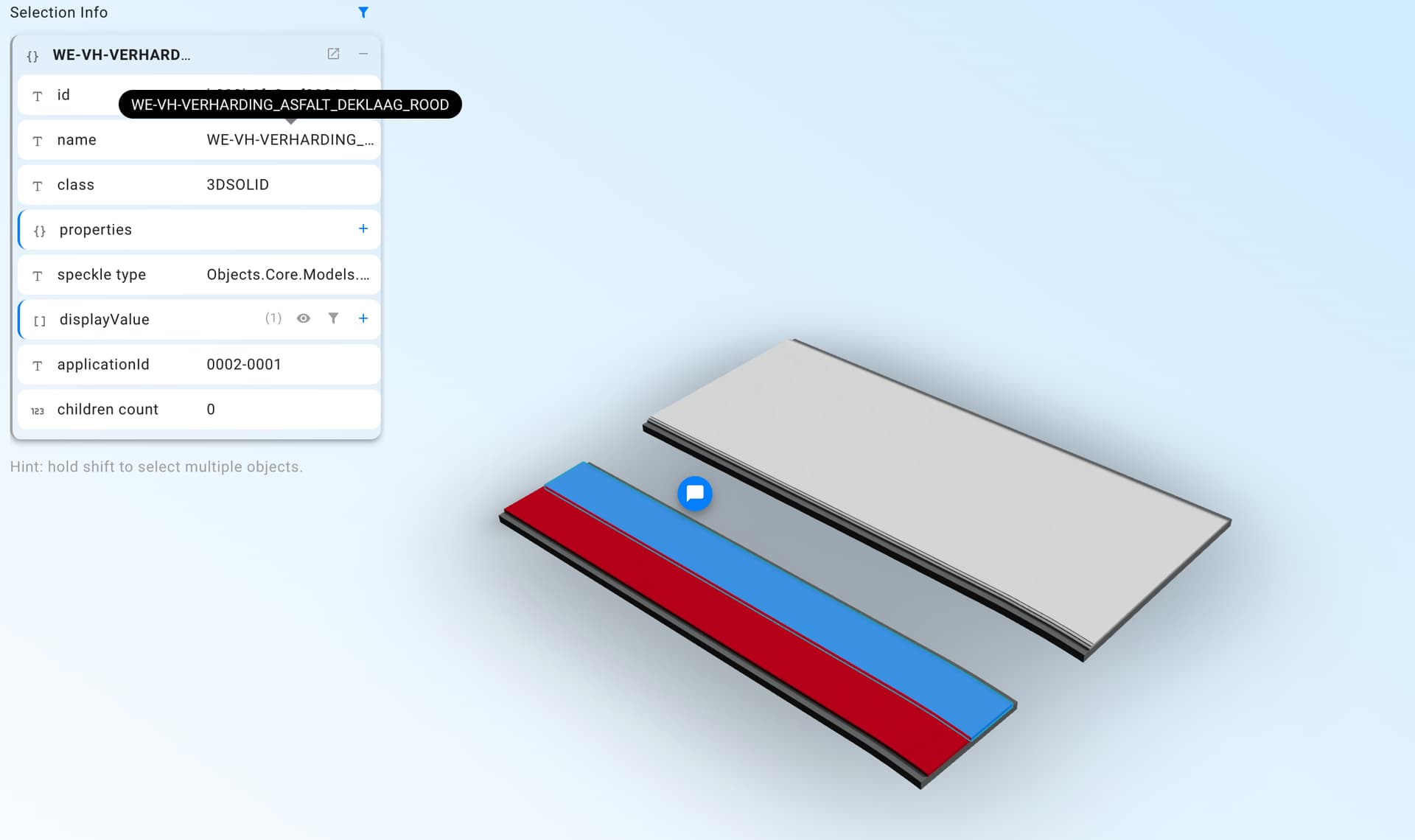
So I have been testing with receiving objects from a stream.
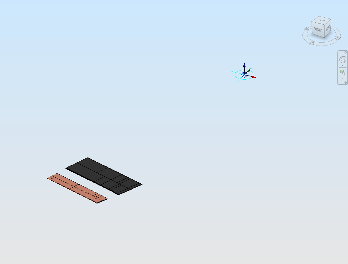
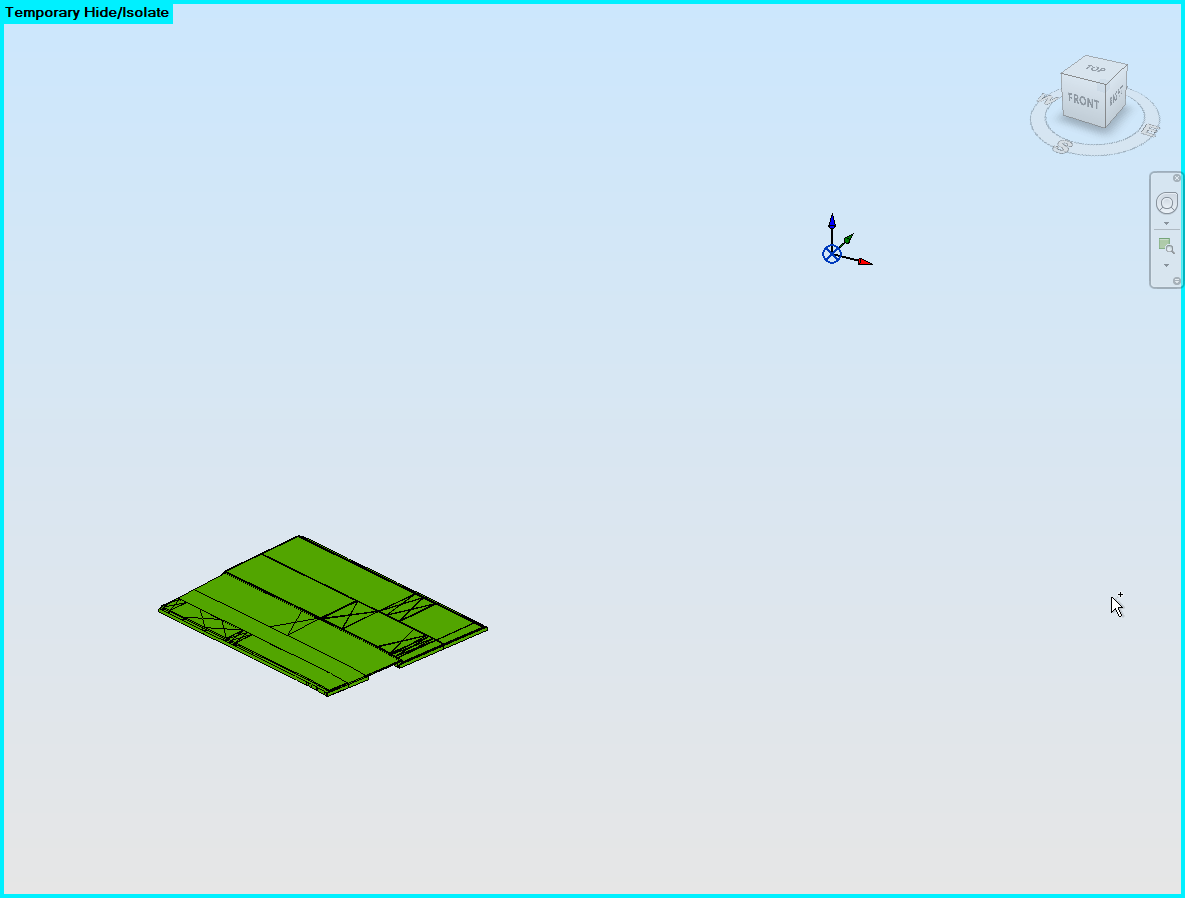
The problem I am having is that when using the “default” Mesh Import Method, the materials of the objects aren’t reflected. For coordination purposes this isn’t really a problem, but the main goal of importing the objects is for drawing production.
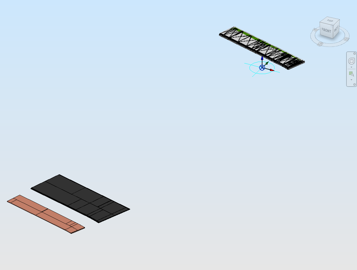
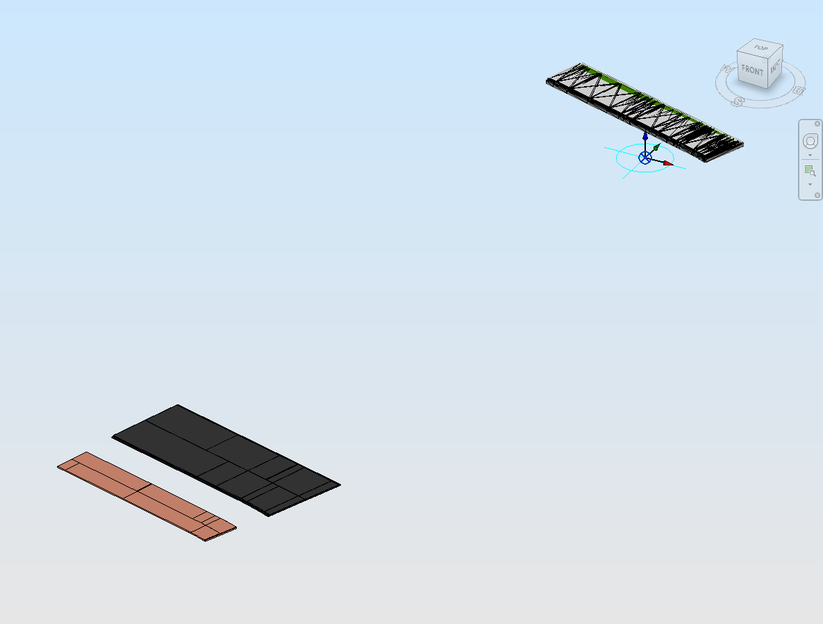
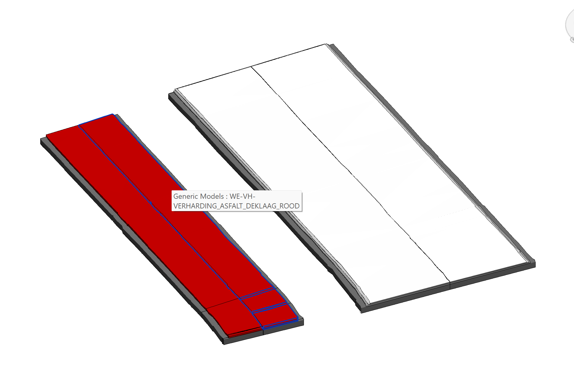
When selecting DXF or Family DXF as Mesh Import Method, the materials are reflected on the created objects, but they aren’t created at the correct location.
Is this a known bug? Does someone recognize this problem?
Or am I doing something wrong?
Maarten
I have added multiple images in which i try to explain it a bit better.
Image with linked CAD in Revit.
Thanks for the detailed explanation and report @MaartenvanderLinden !
As Dick says, it’d be great to have a copy of those CAD files so we can debug internally
The goal is to make sheets which are showing the “external design”.
That means, is am able to change the appearance of the elements. (Visibility / Material)
And be able to dimension the objects.
It isn’t really important for me if it is a Solid or not.
Easiest for us would be to us the Navisworks files to send the geometry to speckle.
Those files are widely available to us. (especially if properties wil be supported)
That would make filtering available in revit.
I am a bit familiar with the revit api and program in c#.
I have taken the liberty to dive a bit in the Revit Connector Code, and I am able to understand parts of it.
I believe I have found the location where the choice is made between the “default, dxf and familydxf” setting for meshes. (ConverterRevit.cs line 528 – 544).
While importing the mesh as directshape (“default”setting) apparently the location of the vertices is corrected by the PointToNative method in CovertGeometry.cs. in which the method ToInternalCoordinates is called (ConversionUtils.cs).
I believe that makes sure that the geometry is created at the “right” position in the revit file.
But at the CreateDxfImport method ( ConverterRevit.DxfImport.cs) I can’t seem to find a method that does the same thing.
While the both methods place the created Dxf directly at de project basepoint (with boudingbox geometry at 0,0,0). I believe the coordinates translation isn’t implemented.
I must say the codebase for speckle is a bit over my head, but I thought I would let you know about my search and findings.
I have some good news for you We’ve improved the way Navis objects get converted in Revit, and hopefully you won’t see this issue appearing in your particular workflow from 2.16 onwards.
We’ve tested your files and they do receive correctly: They will now have the correct material and also display it’s name as it came from Navis.
We’ve also discovered that the issue with the incorrectly located meshes is actually caused by the Revit DXF import. We’re still investigating but it seems like if a DXF doc contains small objects very far away from the origin, Revit is somehow centering those objects on the origin and importing that “smaller” DXF into revit’s document origin.
Obviously, this is not ideal, but we’re still looking into ways to prevent this. If you find this issue again don’t hesitate to let us know about it!
You’ll be able to test the 2.16 release soon so I’ll ping you here once the release-candidate is out!