In our daily work we have to collaborate between Revit and Inventor (or similar type of software - Creo, SolarEdge etc.). Although there are some Autodesk workflows directly baked in Inventor they are not that great for Revit-Inventor model transfer. Mostly we would like to transfer Inventor geometry of every single element (not as grouped by assembly or one huge block).
This lead us to Speckle which unfortunately doesn’t have Inventor connector so we’re testing using AutoCAD as middleware. Unfortunately once we transfer 3D model from AutoCAD to Revit we do get each element split but edges can’t be selectable within Revit dimension tool and Revit elements can’t be snapped to transferred Speckle geometry.
I assume it’s due to how geometry is created from CAD (non solids) but is there any workarounds or plans to upgrade AutoCAD 3D Speckle connector as it can be used as middle stage in geometry transfer from other non supported software.
Also any plans for Inventor connector?
Regardless, kudos Speckle Team for creating this awesome software.
Would it be possible to share with us the files you’re using, or a minimal reproducible version of them, so we can double check on our side:
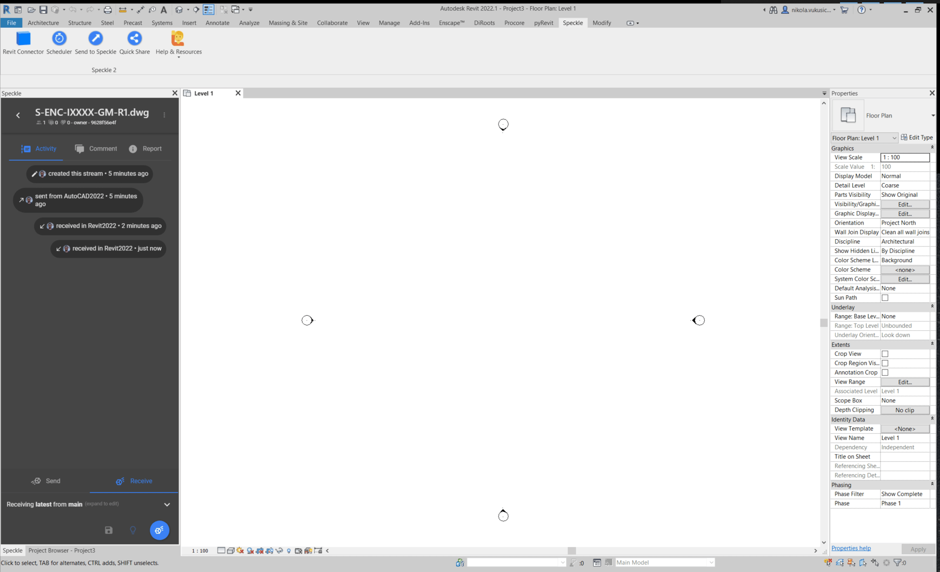
The dwg file you’re sending to speckle
The Speckle stream you’re sending it to
The resulting rvt file when receiving in revit
Some screenshots/gifs would also help us understand better your current use-case. Meanwhile, I’ll ping @clrkng since she’s our AutoCAD
As for an Inventor connector, I don’t recall we have any plans in the near future for this (@dimitrie and @teocomi can correct me if I’m wrong). Mainly because non of us in the Speckle Team come from an Inventor background, so it may take a bit to pick this up.
Since we try to prioritise our community’s needs, we may revise this decision if enough Inventor users make some noise
I have attached documents you mentioned.
Test stream on link below:
Basically everything is transfer as it should but geometry that gets transferred can’t be annotated against or used as reference for aligning other Revit elements to it. This would mean that user would need to zoom in, create reference plane over edge of 3D element and then create dimension line.
This sounds quite painful I’ll think this is because Revit will convert any geometry as a DirectShape, which are not very user friendly objects within Revit…
We do have a couple of other options for geometry conversion, so it may just be a case of picking the right one, but I’ll confess I’m not the most expert in Revit as a user. So I’ll have to try this out.
Meanwhile (I will also try this on my side), the DXF import option may behave differently than DirectShapes in your particular case
Unfortunately you get a lot of other mesh lines (we would only need external lines ) that you may not need which affects visual representation of drawings but I guess you can’t get everything you want
I did notice that export divides lines if they are faces or boundaries. Is it somehow possible to not to export mesh boundary lines? I assume not as these lines are part of DXF meshing.
Interesting! Nice to know the DXF import works for you.
All those lines could be theoretically removed. The way it works is the following:
Each face of the mesh will be created on the temporary DXF file without any edges
Then, for every edge that “doesn’t share 2 faces”, we draw a line. This is done so that we get outlines on meshes that are open (as opposed to just seeing a white blob on your screen), but if the mesh has repeated vertices, this will happen on other faces too.
Since you already sent us the files, I’ll use them to try and come up with a better strategy. At the very least we could add a setting to skip the line creation, but I’d have to check if that would have any undesired effects.
Thanks for the feedback! It’s really valuable to us. We’ll keep you posted on this, and hopefully have an early-release for you to test soon.
I can reproduce this issue on my end as well. Looks like DXF Mesh import method doesn’t hide edges for meshes(?) from AutoCAD. I created an issue for this on Github. Thanks for reporting it🌹!