I have been exploring the .net SDK and was playing around with sending data to a stream.
I have noticed that when I create and object, in this case an Objects.BuiltElements.Civil.CivilAlignment
I don’t get an Alignment object in Object Type filter list. I only get the elements in the curves i.e. Line. And when I select it I can only select the individual curves, not the Alignment.
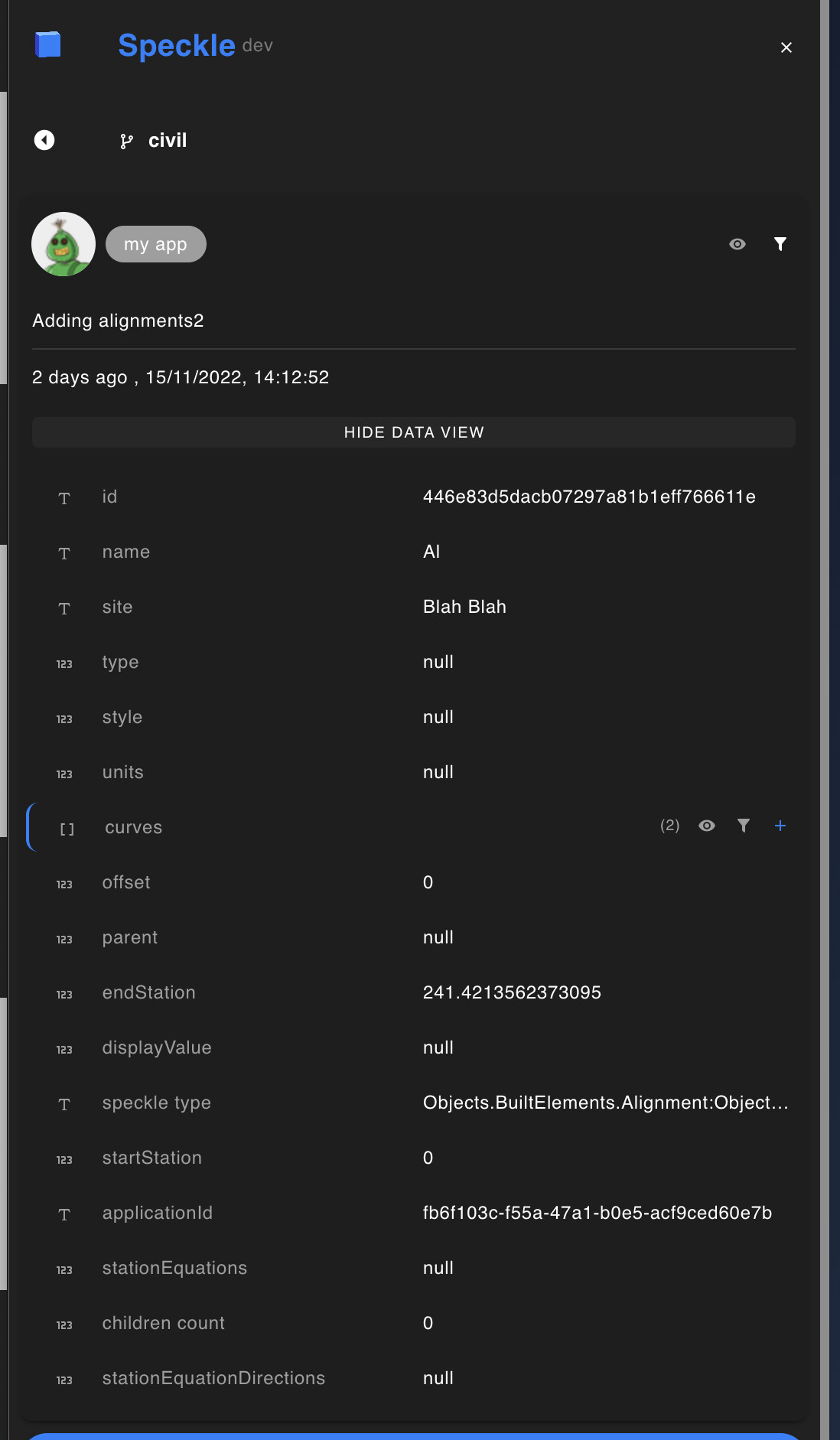
It shows in the Data View as an Alignment but not the filters.
Is there something special I need to do to get this behaviour? This is the very basic test I was doing.
        public static async Task CreateAlignment(string token, string streamId, string branchName)
        {
            var pt1 = new Objects.Geometry.Point(0, 0, 0);
            var pt2 = new Objects.Geometry.Point(100, 100, 0);
            var pt3 = new Objects.Geometry.Point(100, 200, 0);

            var line1 = new Objects.Geometry.Line(pt1, pt2);
            var line2 = new Objects.Geometry.Line(pt2, pt3);

            var speckeAlignment = new Objects.BuiltElements.Civil.CivilAlignment();
            List<ICurve> curves = new List<ICurve>();
            var id = Guid.NewGuid().ToString();

            curves.Add(line1);
            curves.Add(line2);
            speckeAlignment.curves = curves;
            speckeAlignment.startStation = 0;
            speckeAlignment.endStation = line1.length + line2.length;
            speckeAlignment.site = "Road Design";
            speckeAlignment.name = "Alignment1";
            speckeAlignment.applicationId = id;

            var account = new Speckle.Core.Credentials.Account()
            {
                token = token,
                serverInfo = new ServerInfo()
                {
                    url = "http://localhost:3000"
                }
            };

            var client = new Client(account);
            var sw = new Speckle.Core.Credentials.StreamWrapper(streamId);
            var transport = new ServerTransport(account, streamId);

            var objectId = await Operations.Send(
              speckeAlignment,
              new List<ITransport> { transport },
              disposeTransports: true);

            var commitId3 = await client.CommitCreate(
              new CommitCreateInput
              {
                  streamId = sw.StreamId,
                  branchName = branchName,
                  objectId = objectId,
                  message = "Adding alignment",
                  sourceApplication = "My App"
              });
        }
Sorry if I wasn’t clear. I’m talking about in the viewer.
The first image is the alignment I created in the example. Notice that the objects available in the filter are only Line objects, no Alignment. Also when I select the alignment it selects the individual Curve element (Line). The second images is the alignment in the Data View I mentioned.
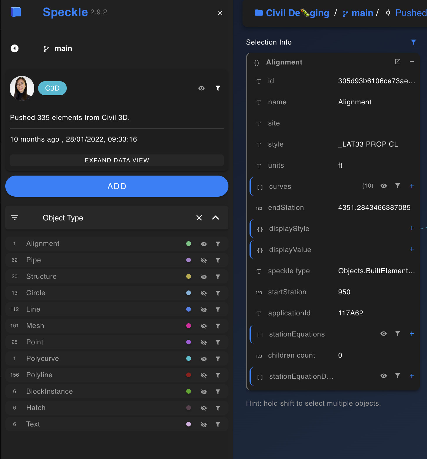
The next one is from a public stream I came across where the alignment is converted using the Civil 3d Connector. You can see that when selected it selects the whole alignment and it also shows up in the objects to filter.
Hi Jason, there’s a couple of things going on with the the viewer that you are observing.
You are correct that the Civil3D connector is making the same Alignment elements that you are creating programmatically - typologically the same at least.
Speckle Connectors include a displayValue property. Yours report null. Where this becomes significant is how the Viewer, (which doesn’t know a Wall from a Beam from a Pipe) makes sense of what to show. It uses the displayValue property to determine geometric data objects from non-geometric data objects.
You can read more in our documentation : Displaying Base but in short, this behaviour stems from the fact that any property of a Speckle object can also be a Speckle object or collection of Speckle objects.
Without it it keeps traversing the property tree until it finds something it “understands”; in this case a Line. It is the collection of these objects it finds that are available to the filtering engine where all properties of those objects become filter options.
Take a look at the members of the displayValue coming from Civil3D and see if it helps. Check back here if you have further questions.
You are correct in that the displayValue for Alignment was not being set previously, because the viewer logic should be able to display the curves from the curves property directly. You shouldn’t have to worry about adding a displayvalue! After a quick test, sending a CivilAlignment currently does result in the same viewer filter behavior you are experiencing as you can see here: Speckle
I’ll ping the web team to see if there have been changes to the viewer handling or if the new CivilAlignment subclass change (previously alignments from Civil3D were just sent as generic Alignment objects instead of CivilAlignment) somehow isn’t being handled correctly with the current selection logic
Okay, so the original reasoning behind removing the displayValue for Alignment was due to Civil3D basecurve approximations being quite rough, and those misleading display polylines in the viewer caused concern for a few civil engineers.
Removing the displayValue does result in the filter behavior you are seeing and that @jonathon explained however, so for your purposes if it’s important to have your alignment registering as a single entity in the viewer, you can add in the displayValue like so:
// create a flat list of point coordinates for your lines
var coordinateList = new List<Point>() { pt1, pt2, pt3 }.SelectMany(p => p.ToList());
// set alignment display value polyline
speckleAlignment.displayValue = new Polyline(coordinateList);
With more complex alignments that have for example Arc or Spiral segments, this is going to be much harder to do mathematically, though if you use the Civil3D API you can get a rough polyline approximation of the basecurve like so:
var polyline = civilAlignment.BaseCurve.Spline.ToPolylineWithPrecision(1, true, true);
Here’s the difference between using and not using a displayValue for an alignment from Civil3D:
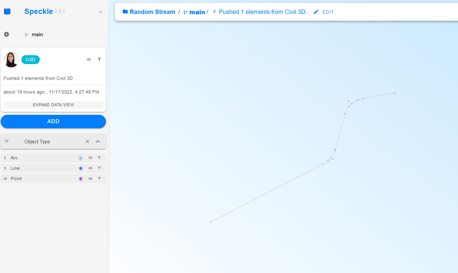
CivilAlignment without a display value, curves are accurate in the viewer but the alignment is not registered as displayable and you see nested curve types in the filter instead
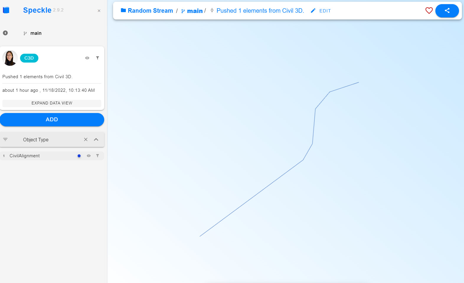
CivilAlignment with a basecurve polyline display value, looks inaccurate in the viewer but the alignment is displayable and you see the alignment type in the filter